Is Calderdale Energy Park properly designed?
In this article we shall see that Calderdale Energy Park is not the result of a proper design process and it was therefore unlawful under the Gunning Principles to present it for Public Consultation.
A turbine extracts energy from the wind, so behind the blades is a wake of slower moving, turbulent air. Practical wind farm aerodynamics is about getting the next downwind turbine far enough away that the wake has filled with fresh fast air. Because wind flow over rough terrain is so complicated, all wind farm designers use a simple method to achieve a compromise between wake losses and the price of land.
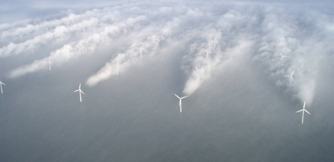
Wakes behind wind turbines. The wakes spread and weaken with distance. Photo: Charles Meneveau.
Designers start with the rotor diameter (RD) of the turbines, which is twice the blade length. The RD appears in the product names, like the Vestas V162-7.2 MW with a 162 m RD, the minimum for a CEP turbine. Were the site less wuthering, the Vestas V172-7.2 MW with a 172 m RD might have been chosen.
The rule used by UK wind designers is that the turbines are spaced a minimum of 3 RD apart in the rows facing the prevailing wind, and a minimum of 5 RD apart down wind.
Whitelee wind farm (529 MW) is south of Glasgow is 529 MW and 10% of the huge layout is shown below. It was properly designed from the start. In each 3 RD by 5 RD rectangle, the small circle shows the blade circle to scale, and the slanting lines show the wake getting weaker. The wind is shown coming from the SW, the prevailing wing over the UK.
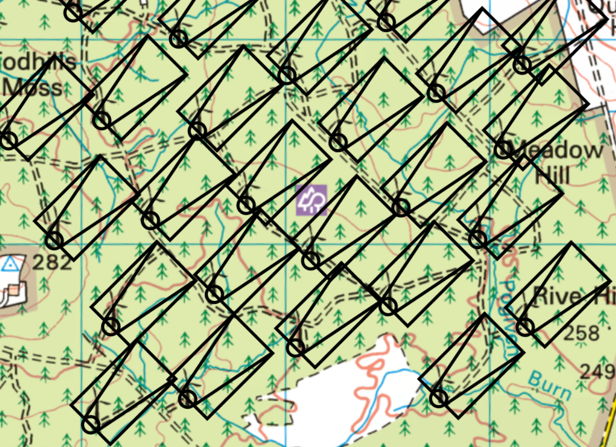
One tenth of the huge Whitelee WF (529 MW) off M77 south of Glasgow, showing the 3 RD by 5 RD footprints. The circle shows the rotor diameter and the spreading lines show the wakes. Map: Nick MacKinnon
The next map is Scout Moor, which has Pennine terrain like Walshaw Moor, and was properly designed from the start.

Scout Moor WF (65 MW) has the terrain that is most like CEP. The turbines are well-spaced using a 3 RD by 5 RD footprint as we would expect from a reputable developer. Map: Nick MacKinnon
Our third example is Viking Shetland WF The terrain is not like the Pennines. The huge 443 MW wind farm is on an archipelago of short ridges connected by tracks and public roads. After the layout was done the turbines were uprated without any resiting and the wind farm is overcrowded, which is one reason why Viking Shetland has been so controversial. Turbine manufacturers want to sell more turbines and wind farms want the highest possible installed power, because this determines the constraint payments, when they stop generation because the grid cannot use the electricity so both parties like overcrowding. Constraint payments to Viking Shetland are already notorious and Prime Minister Keir Starmer has spoken firmly to the wind farm designers. Electricity bill payers must have efficient wind farms and no constraint payments. Viking Shetland is scandalously overcrowded and the regulator failed every bill-payer in the UK.
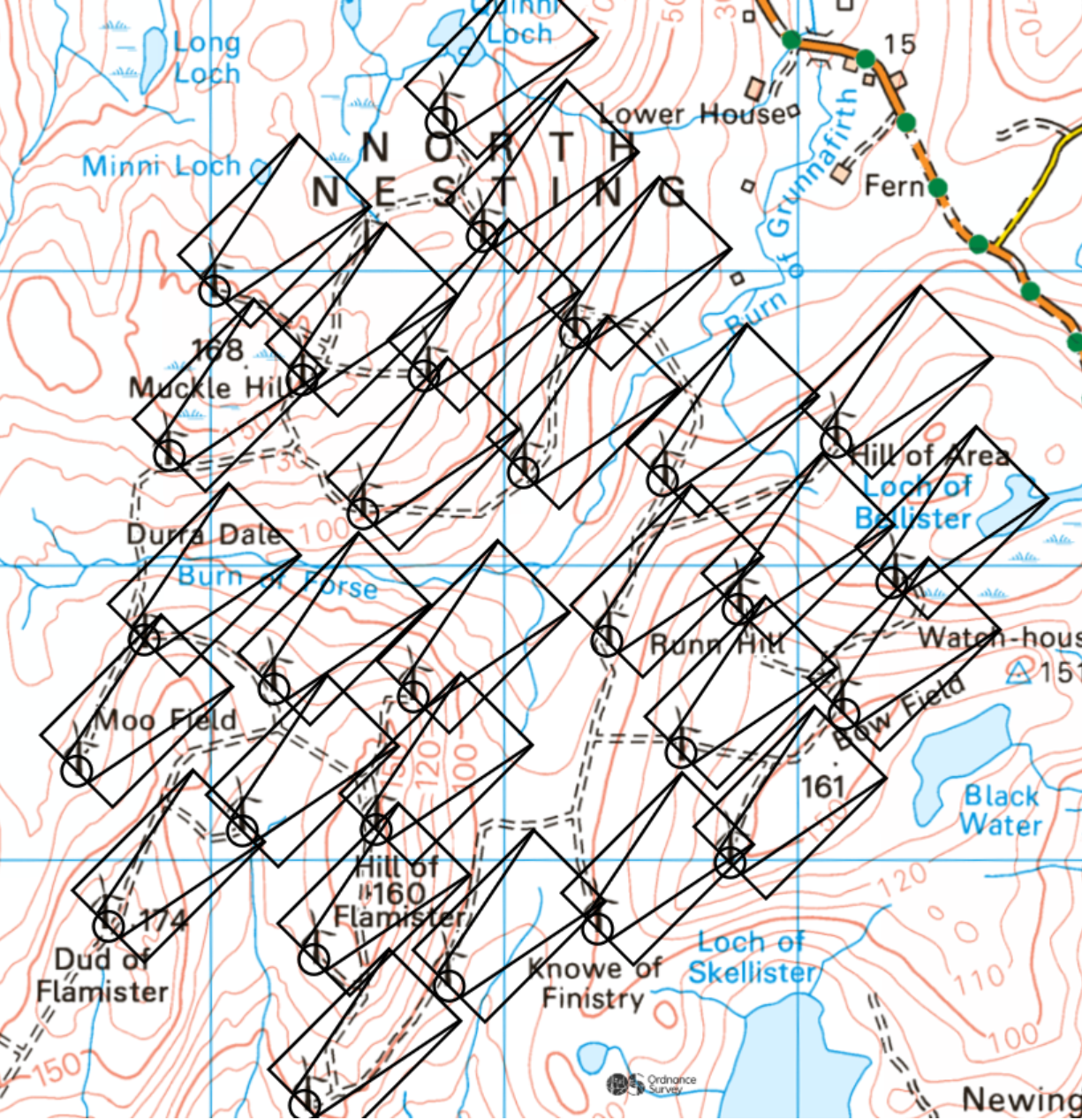
Part of Viking Shetland WF (443 MW). This wind farm is laid out as an archipelago, making use of the public road system to link the islands. Although it was laid out on a 3 RD by 5 RD footprint, the wind farm is scandalously overcrowded. Map: Nick MacKinnon
Whitelee, Scout Moor and Viking Shetland are built on very different terrain and subject to wind forces, and have different turbines, but they all conformed when designed to a 3 RD by 5 RD footprint. No supercomputers solved the massive problem of air flow over rough terrain. The designers simply applied the 3 RD by 5 RD rule of thumb, and they did this first. What went wrong at Viking was the failure to redesign the layout when the turbines were uprated.
We turn to Calderdale Energy Park and use the same 3 RD by 5 RD footprint on the 162 m rotor diameter of the huge turbines. We see at once that CEP Layout is grossly overcrowded by the standards of reputable developers and is far more so even than scandal-hit Viking Shetland.
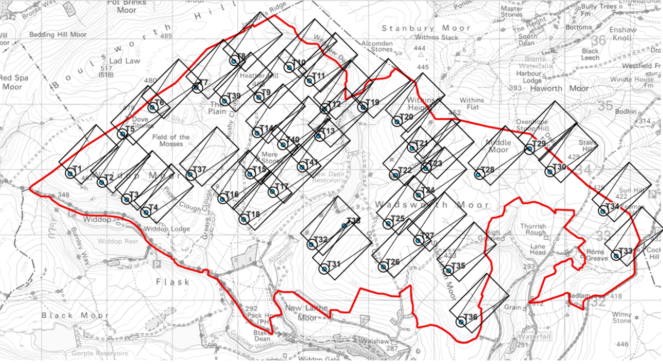
As we would expect from a company with no reputation, CEP is grossly overcrowded, especially on Heather Hill and south of Wuthering Heights in the T21-T24 cluster. It is hugely more overcrowded even than the scandalous Viking Shetland. Map: Nick MacKinnon
You may be wondering how grossly overcrowded the original CWF 65-turbine proposal must have been. Surely with 65 turbines the wakes must have been piled up like corpses in a plague pit …
The CWF turbines were smaller. CWF was properly laid out for aerodynamics by the reputable company Natural Power to the usual 3 RD by 5 RD spacing. That CWF had correct aerodynamics is the most convincing evidence that something went terribly wrong at the CEP design meeting on 22 February 2025. There was a lot wrong with CWF too, and it was going to be mitigated down to a nubbin, but it started with an aerodynamically correct layout.
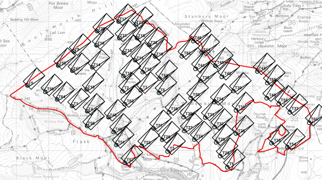
The layout of the collapsed Calderdale Wind Farm was correctly spaced by an expert designer at Natural Power. That they used the 3 RD by 5 RD spacing is clear in the map. One reason for the collapse of the CWF proposal were grave errors in the public statements of the management of CWF Ltd, but these were not the fault of Natural Power who are a wholly reputable company. Map: Nick MacKinnon
The 65-turbine CWF has been described by the CEP consultant Donald Mackay as “worse than useless” but at least it was properly laid out to catch the wind efficiently by industry standards.
Properly designed wind farms are planned on a 5 RD downwind spacing from the start.
Garn Fach WF (Powys, 85 MW, approved October 2024) is of particular interest because it was developed by EDF when Christian Egal (CEP Project Director) was CEO of their UK renewables. The Environmental Impact Statement for Garn Fach WF states:
4.2.2 Design parameters for the scheme were established at the commencement of the project (i.e. 5 x 3 rotor diameter spacing of wind turbines, tip height 149.9 metres to avoid fixed visible light).
Readers can judge for themselves whether EDF met their own design standard.
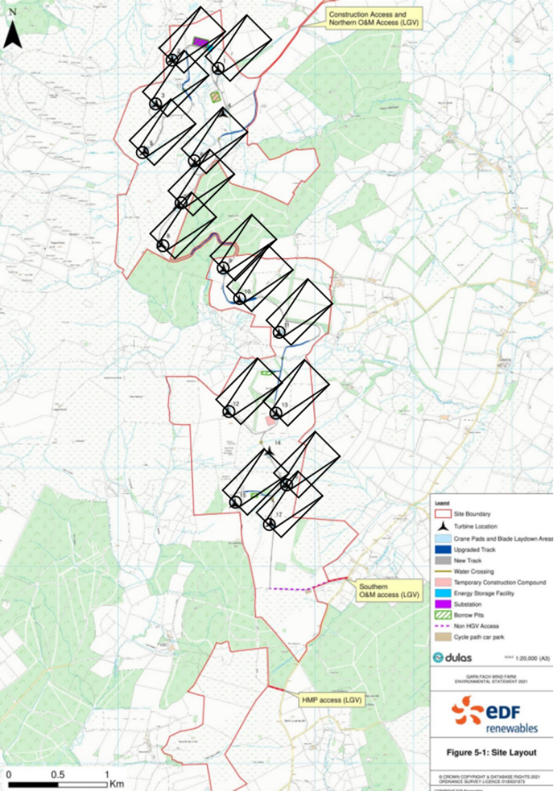
Garn Fach WF in Powys was designed when Christian Egal was CEO of EDF Renewables Is it overcrowded? Juste un peau. Map: Nick MacKinnon
For Carrick windfarm (Galloway, 86 MW) the environmental impact statement says:
“44: There is no industry standard for spacing, only manufacturer recommendations, and operational experience. Referring to onsite wind measurement data, it was confirmed by the Applicant that there are high percentages of wind direction from NW, through SW and SE of the site. As a result, a spacing of five times rotor diameter in all wind directions was applied for the Proposed Development.”
Scientific research shows that 5 RD is much too close for efficient harvesting of the wind, and 15 RD has been shown to be best. Until the regulator gets a grip, electricity bill-payers must pay for overcrowding, but nobody should have to pay for such a grossly over-stuffed as CEP and no expert wind farm designer would ever offer such useless layout for Public Consultation.
The lawyers for CWF Ltd have been unable to supply arguments that the public consultation was lawful under the Gunning Principles. The matter is now lodged with the Planning Inspectorate. Until the CWF Ltd lawyers prove otherwise, no lawful Public Consultation into CEP has been held.
